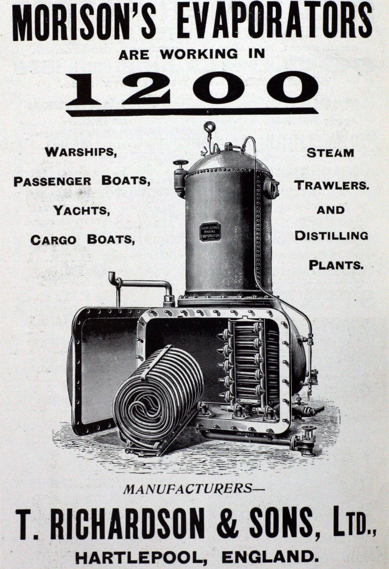
Evaporators
- Evaporators are a common process whenever large amounts of water or another solvent are to be separated from relatively non-volatile components.
- They function by simply boiling the volatile component away.
- They are often seen when large amounts of fresh water are required. For example, drinking water on ships or for steam ship boilers ( top product).
- Evaporators are also used to concentrate aqueous solutions such as fruit juice or orange juice (bottom product).
- They are common when the process fluid contains precipitates that need to be crystallised.
- We study evaporators first in this course as they are essentially an ideal flash-distillation step (there is a perfect separation of the components). No need to worry about the phase equilibria part of thermodynamics (yet).
- Later on, we will have to calculate how much of the two (or more) species is present in the top and bottom product using vapour-liquid equilibrium data, or solubility data.
- However, in this course, the defining characteristic for evaporators is that we will assume all of the involatile components (e.g., salt, solids) are recovered in the bottoms product.
- There are many designs of evaporator, but there are some fundamental operational classifications.
- Evaporators may be single-pass, where the fluid is heated only once, or recirculating, with a long residence time of the treated fluid.
- Evaporators may also operate in convective or boiling regimes depending on the state of the fluid at the heat source.
- The flow around the heat source may be natural or forced.
- We'll look at some common designs now to get a feel for the evaporator process equipment. While looking, try to see why the vapour and liquid outlets might be considered "well-mixed" and in equilibrium.
There are many designs of evaporator:
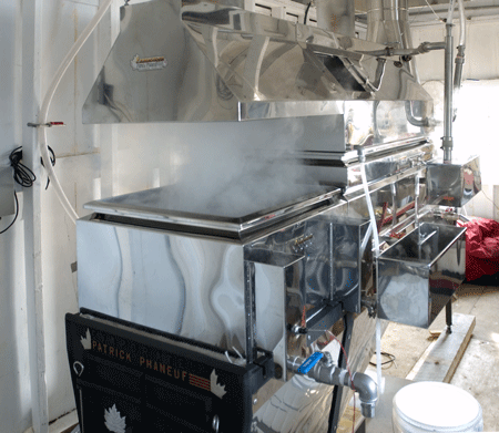
- There is the open-kettle or pan which is a simple evaporator.
- It is usually heated through a jacket or coil, and may be directly fired.
- They are inexpensive and simple to operate, but the efficiency is poor.
- They are common for small scale or old/traditional process designs.
- For example, old salt pans used in salt mines or traditional maple syrup refiners (see right).
- No longer used except for "traditional" (i.e., inefficient) production.
There are many designs of evaporator:
- A common and simple design is the horizontal-tube natural circulation evaporator.
- The heating steam is condensing on the tube side and the tube bundle is completely submerged in the liquid.
- They are simple designs which are relatively easy to clean.
- These evaporators are good for low-viscosity fluids with high heat transfer coefficients, as it relies on natural convection.

There are many designs of evaporator:
- There is the vertical-tube natural circulation evaporator.
- In this evaporator, the boiling liquid is on the tube side, but also flows around the tube bundle in a downcomer (multiple pass).
- The heating of the fluid in the tubes causes natural convection to occur.
- This pumps the liquid up the tubes increasing the liquid velocity and the heat transfer coefficient.
- As such, this design cannot be used with viscous liquids, but it is more efficient than the kettle type evaporator.
- The lower portion of the evaporator is known as the calandria.


There are many designs of evaporator:
- There is the long-tube vertical-type evaporator.
- The tubes can be 3 to 10m high and the liquid may only pass through the evaporator once ( single-pass).
- Boiling causes vapour bubbles to form which pump the liquid at high velocities through the tubes.
- Contact times can be low, which is useful in the food industry (no burning of the product).

There are many designs of evaporator:
- A variation on the long-tube vertical-type evaporator is the vertically fed falling film type evaporator.
- Gravity and expansion of the fluid greatly increase the fluid velocities.
- These can be designed with very short contact times.
- This is an advantage as damage to sensitive heat-treated fluids is a function of temperature and contact time.

There are many designs of evaporator:
- There are also forced-flow evaporators.
- These may exploit the pressure of a liquid head to prevent boiling in the exchanger.
- They may also have a circulating pump to force the flow, or they may rely on the thermosyphon effect.
- This is an analogue of the chimney effect, where a strong form of natural convection is used to pump a fluid.
- Despite the “natural” origins of the thermosyphon flow, the fluid is being strongly forced through the heat exchanger.

There are many designs of evaporator:
- Finally, for viscous fluids, there are evaporators which mechanically coat the heated surface with the fluid (agitated-film).
- This ensures good heat transfer regardless of the viscosity and can be used for the drying of very thick pastes.
- Deciding which evaporator to use strongly depends on the cost of materials, energy and fluid properties.
- Luckily, there are many case studies in the literature which have been collated into tables to aid you in the selection of your evaporator…


- A common feature of all types of evaporators are deentraining devices such as baffles.
- These reduce or prevent entrained droplets of liquid exiting in the top stream.
- Evaporators are also typically operated as total-condensers on the steam side (only condensate/water is removed from the steam side). This greatly simplifies the heat balance on the steam side, as its the latent heat of steam vapourisation/condensation.
- When designing your evaporator, you start with a feed stream, and you have to achieve an output specification.
- For example, you have a feed stream of 1000 kg/hr of orange juice with a solids concentration of 7.08% w/w.
- You need to concentrate it to 50% w/w solids content before it is economical to ship it overseas.
- How big should our exchanger be to achieve this? What is the heat transfer area required? What utilities (steam) will be used? What is the overall duty of the evaporator?
- Single-stage evaporators are, essentially, a heat exchanger and we roughly size heat exchanges using their area.
- To find the size of the evaporator, we need to solve the heat transfer equation for the heat transfer area, A : \begin{align*} Q = U A \left(T_{steam} - T_{fluid}\right) \end{align*}
- We need to find the duty, Q, the heat transfer coefficient U, the boiling temperature of the evaporator Tsteam, and the steam temperature.
- The steam temperature is set by the available utilities, and the heat transfer coefficient/area can be calculated together from our Heat, Mass, and Momentum knowledge once the duty is known.
- So we must first compute the duty, Q, and we need a simple model of our evaporator to do this…

- Our simple model for the evaporator is that it has one input stream, and two output streams.
- All of the solids entering in the feed stream F, is recovered in the liquid stream, L.
- No heat is lost or gained during this process, except by that removed or supplied by the duty, Q.
- With the initial design data, we can see that there are two unknown flowrates of streams we need to solve, L and V.
- We need the fundamental equation of process engineering, the balance equation : \begin{align*} \textrm{INPUT}-\textrm{OUTPUT}+\textrm{GENERATION}=\textrm{ACCUMULATION} \end{align*}
- Taking a total mass balance and a mass balance in the solids content we have \begin{align*} F &= L + V & x_{s,F} F &= x_{s,L} L \end{align*}
- These equations are our general balance equations for an evaporator.
- Taking the solids balance, we have \begin{align*} x_{s,F} F &= x_{s,L} L\\ 0.0708\times1000 &= 0.50 \times L\\ L &= 0.0708\times1000 / 0.5 = 141.6 \textrm{kg/hr} \end{align*}
- Using the total balance, we have \begin{align*} F &= L + V\\ 1000 &= 141.6 + V\\ V &= 1000 - 141.6 = 858.4 \textrm{kg/hr} \end{align*}
- We'll now update our diagram…

- To calculate the duty, Q, we need to perform an energy balance to obtain… \begin{align*} \textrm{Energy In} + \textrm{Duty} &= \textrm{Energy Out}\\ F h_F + Q &= L h_L + V h_V \end{align*} where $h_F$ is the enthalpy per mass for the feed stream, $F$.
- The enthalpies, $h$, for each stream depend on temperature AND composition!
- The most difficult part of evaporator design may be tracking down accurate values for the stream enthalpies.
- The difficulty is that there is an infinite selection of mixtures and a very limited amount of experimental data.
\begin{align*} \textrm{Energy In} + \textrm{Duty} &= \textrm{Energy Out}\\ F h_F + Q &= L h_L + V h_V \end{align*}
- We will look at enthalpy and boiling point data in a later lecture, and will make some simplifying assumptions for now...
- Let's assume that the inlet stream is at its boiling point ($100^{\circ}C$ @ 1atm) and the solids concentration does not affect the boiling temperature.
- We also assume that there is no enthalpy of mixing ( concentration does not affect the enthalpy, $h_F=h_L$).
- Then the only enthalpy difference will come about due to the boiling of the water content.
\begin{align*} F h_F + Q &= L h_L + V h_V \end{align*}
- Using $h_F=h_L$ and $F-L=V$, the energy balance yields: \begin{align*} Q &= V \left(h_V - h_L\right) \end{align*}
- We have from the steam tables $h_V-h_L=2260$ kJ/kg at 100 ${}^\circ$ C, therefore \begin{align*} Q &= 858.4\times2260\approx1.9\times10^9\textrm{J}\,\textrm{hr}^{-1}\approx540\textrm{kW} \end{align*}

\begin{align*} Q &= U A \left(T_{steam} - T_{fluid}\right) \end{align*}
- To calculate the evaporator size, we need the overall heat transfer coefficient, and the temperature difference.
- The overall heat transfer coefficient depends on the evaporator type, operating method and flow velocities (see Heat, Mass, and Momentum Transfer.).
- You will probably have to iterate to a solution to $U$ in a detailed design (just like your design project).
- But there are typical values available in the literature…
| Type | Overall U (W/m ${}^2 $ K) |
| Short-tube vertical, natural | 1100–2800 |
| Horizontal-tube, natural | 1100–2800 |
| long-tube vertical, natural | 1100–2800 |
| long-tube vertical, forced | 2300–11000 |
| Agitated film | 680–2300 |
\begin{align*} Q &= U A \left(T_{steam} - T_{fluid}\right) \end{align*}
- Finally, we need the temperatures of the evaporator.
- The temperature of the evaporator fluid depends on the solvent boiling point and an effect called boiling point rise.
- For simplicity, we can assume at low concentrations the boiling point is the same as for the pure solvent. \begin{align*} T_{fluid} = T_{sat.,solvent} = 100^\circ\textrm{C} \end{align*}
\begin{align*} Q &= U A \left(T_{steam} - T_{fluid}\right) \end{align*}
- The temperature of the steam depends on its saturation temperature. \begin{align*} T_{steam} = T_{sat.,steam} \end{align*}
- This is because the latent heat of condensation of the steam is used to heat the evaporator (the condenser is a total steam condenser).
- The saturation temperature depends on the pressure of the available steam, and can be looked up in your steam tables.
- To calculate how much steam, $S$, the evaporator will use, we will need another heat balance: \begin{align*} Q &= S \left(h_{steam,vapour} - h_{steam,liquid}\right) \end{align*}
- However, if we assume that steam has a latent heat of vaporisation with only a weak temperature and concentration dependence, the amount of steam condensed will be the same amount of water evaporated! \begin{align*} S \approx V \end{align*}
- This concludes our roughest design of an evaporator, we will improve this calculation in the coming lectures.